Writing an .stl file from scratch
The .stl file format (see also) is used for 3D printing and similar fabrication technologies. The files are normally created as output from design software, but I wanted to try writing one by hand since they are human readable (actually, both ASCII and binary versions are allowed by the file-type specifications—obviously my attempt was in ASCII). I thought this would be a good exercise to practice some vector math I haven't used in a while. Furthermore, understanding the steps in writing .stl files is useful if you want to create your own program to output 3D-printable files.
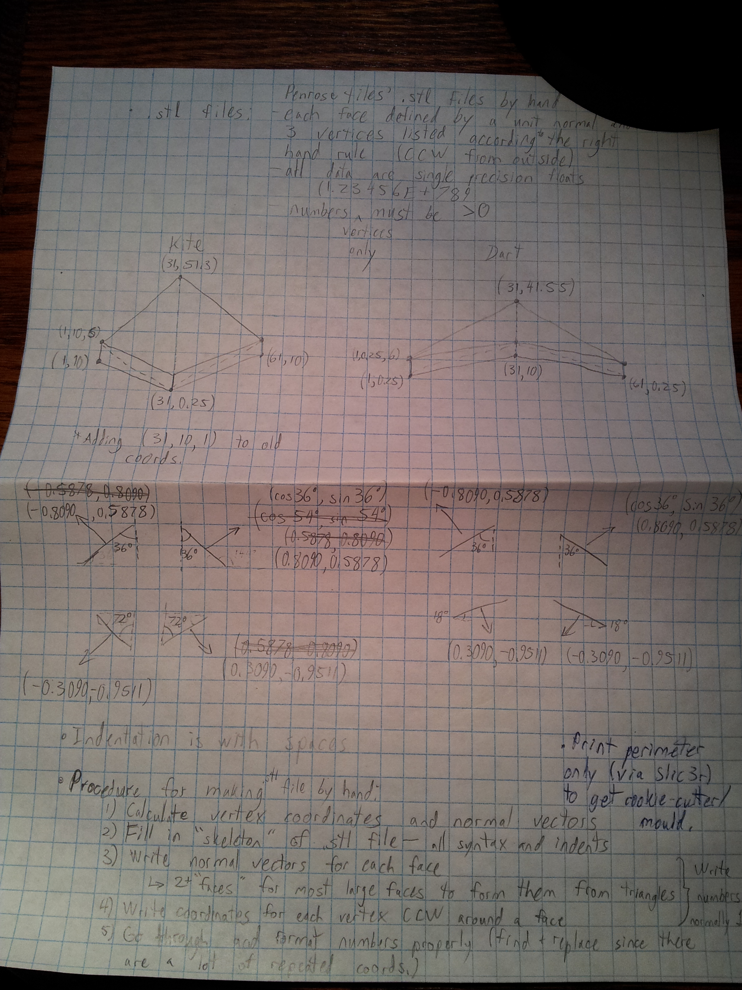
The structure of an .stl file is a hollow shell of triangular faces. Each face is defined by three points (x,y,z coordinates of the vertices of the triangle) and a normal vector pointing out of the shell perpendicular to the face. Additional restrictions are that the points must be listed in the order indicated by the right-hand rule (i.e. counterclockwise when viewed from outside the shell) and that all points must be greater than zero. Scientific notation should be used for each coordinate of the vertices and vectors.
The syntax of an .stl file is simple. It begins with the word solid and the name of the object. Then each facet is stated. First the normal vector is given then each vertex on the outer loop of the triangular face. Coordinates are separated with spaces rather than commas or any other punctuation. Except for the statements of normal and vertex, each term in the file has a balancing end statement: endloop, endfacet, and endsolid. In the example shown below, the structure and syntax of an .stl file should be pretty clear. Indentation is with spaces.
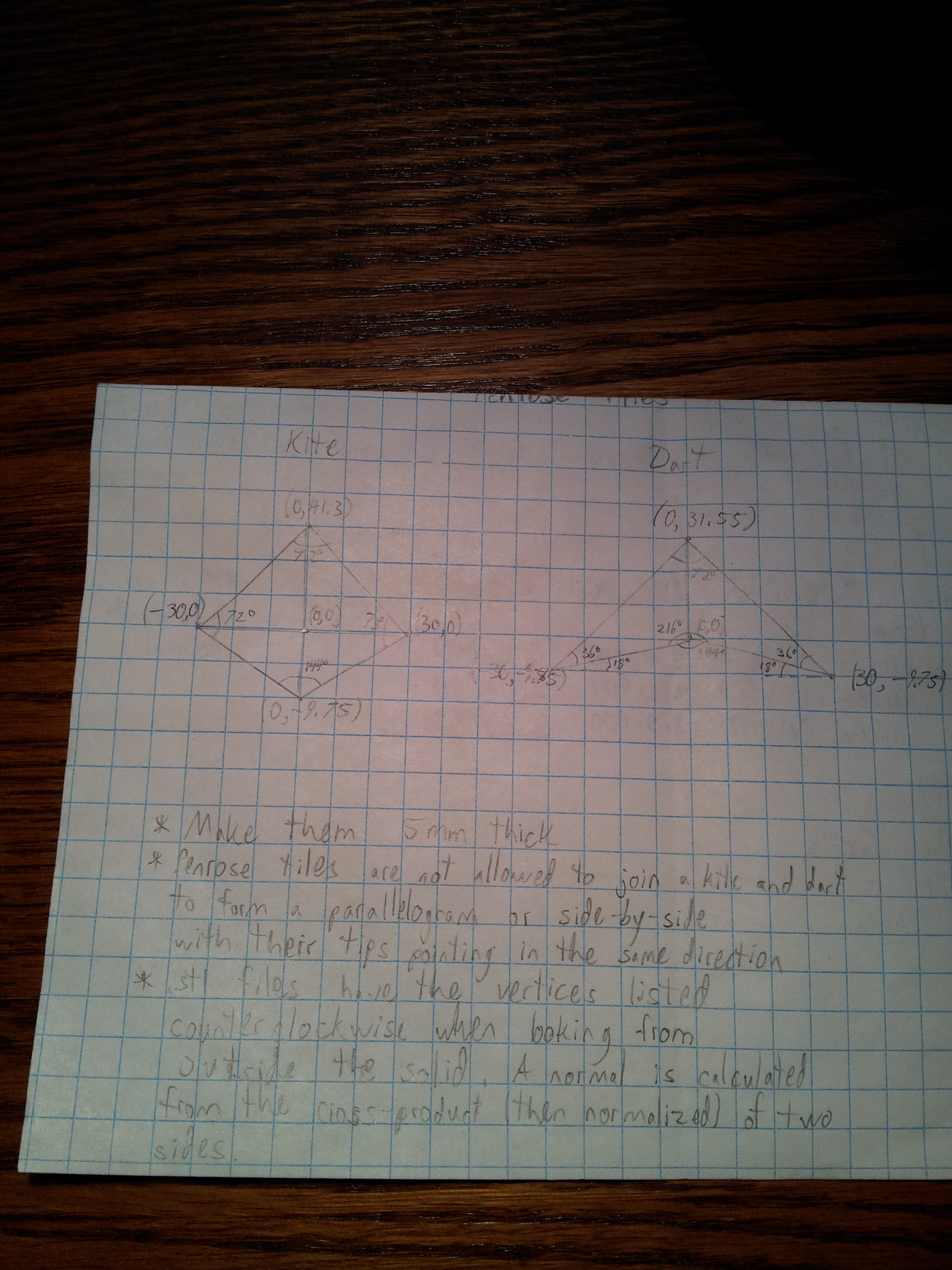
For my example .stl file, I chose the Penrose kite and dart tiles. I find Penrose tilings very interesting because they have both order and complexity. The tilings have a lot of repeating elements but never repeat overall in a way that would allow the whole design to be shifted any distance in any direction and find a perfect match. Tiling in general is an interest of mine (inspired by some scenes in Anathem and a visit to Spain), so watch for future posts on the subject as well.
Here's the procedure I followed to write the .stl file manually:
- First I drew sketches of the objects I wanted to describe and calculated the coordinates of each vertex and normal vector. For these tiles, I picked a width of 60 mm and then calculated all of the other dimensions from the angles of the tiles. In general, the normal vectors could be calculated as a normalized cross product of two sides of each face, but all of my normal vectors were either in the x,y plane or along the z-axis, so I simply used trigonometric ratios. Finally, I had to shift all of the vertex coordinates into the positive octant and divide quadrilateral faces into two triangles each.
- Fill in the skeleton/structure of the .stl file in a text editor.
- Write the normal vectors for each face.
- Write the coordinates of each vertex for each face, in counter-clockwise order as seen from the outside.
- Because I wrote the numbers plainly to start with (to make it easier to read while I was working), I had to fix the formatting so they were written in scientific notation. This was accomplished quickly with find and replace since each coordinate is shared by multiple faces.
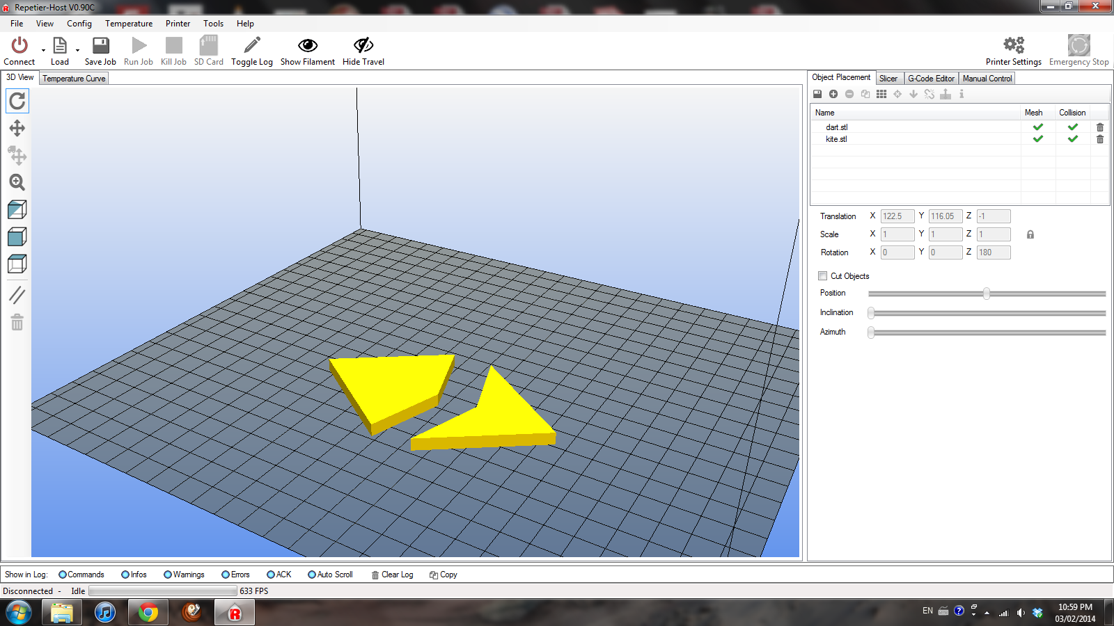
- After the .stl file was saved, I loaded it into Repetier Host to check that it looked okay.
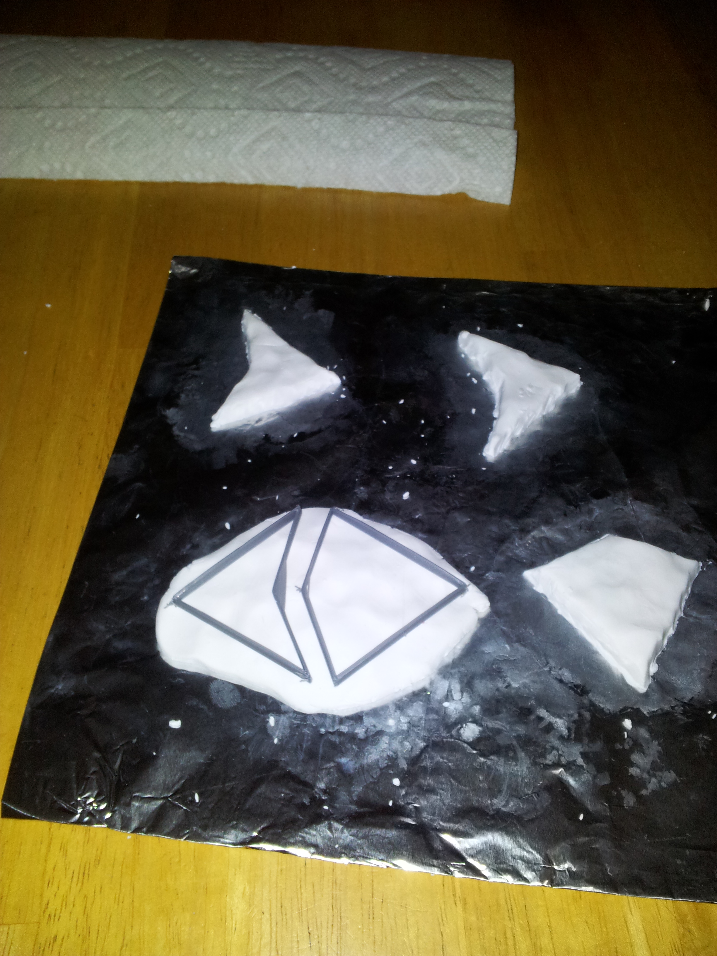
- I printed the tiles out, using slicer settings with no infill, no bottom layer, and no top layer (i.e. perimeter only) to get a "cookie-cutter" result.
- Using the printed "cookie-cutter" tile perimeters and some modelling clay (a synthetic kind that can be fired in a home oven), I was able to make several tiles.
The last step illustrates an area where I feel 3D printing has a lot of potential. By using it to make customized moulds or forms, then switching to more traditional materials and methods (e.g. clay, woodworking), you can take advantage of both the precision and customizability of 3D printing, as well as the greater speed and different material properties of other techniques.
The rest of this post contains the sample .stl file I wrote plus some pictures of my rough sketches and calculations, the files loaded into the 3d printer host software, and making some moulded tiles with the printed perimeters.
(Save the following code as dart.stl; the code for it and the kite tile can also be downloaded from Thingiverse):
solid dart
    facet normal 0.00000E+000 0.00000E+000 -1.00000E+000
        outer loop
            vertex 3.10000E+001 4.15500E+001 1.00000E+000
            vertex 3.10000E+001 1.00000E+001 1.00000E+000
            vertex 1.00000E+000 2.50000E-001 1.00000E+000
        endloop
    endfacet
    facet normal 0.00000E+000 0.00000E+000 -1.00000E+000
        outer loop
            vertex 3.10000E+001 4.15500E+001 1.00000E+000
            vertex 6.10000E+001 2.50000E-001 1.00000E+000
            vertex 3.10000E+001 1.00000E+001 1.00000E+000
        endloop
    endfacet
    facet normal 8.09000E-001 5.87800E-001 0.00000E+000
        outer loop
            vertex 3.10000E+001 4.15500E+001 1.00000E+000
            vertex 6.10000E+001 2.50000E-001 6.00000E+000
            vertex 6.10000E+001 2.50000E-001 1.00000E+000
        endloop
    endfacet
    facet normal 8.09000E-001 5.87800E-001 0.00000E+000
        outer loop
            vertex 3.10000E+001 4.15500E+001 6.00000E+000
            vertex 6.10000E+001 2.50000E-001 6.00000E+000
            vertex 3.10000E+001 4.15500E+001 1.00000E+000
        endloop
    endfacet
    facet normal -8.09000E-001 5.87800E-001 0.00000E+000
        outer loop
            vertex 1.00000E+000 2.50000E-001 6.00000E+000
            vertex 3.10000E+001 4.15500E+001 6.00000E+000
            vertex 3.10000E+001 4.15500E+001 1.00000E+000
        endloop
    endfacet
    facet normal -8.09000E-001 5.87800E-001 0.00000E+000
        outer loop
            vertex 1.00000E+000 2.50000E-001 1.00000E+000
            vertex 1.00000E+000 2.50000E-001 6.00000E+000
            vertex 3.10000E+001 4.15500E+001 1.00000E+000
        endloop
    endfacet
    facet normal 3.09000E-001 -9.51100E-001 0.00000E+000
        outer loop
            vertex 1.00000E+000 2.50000E-001 6.00000E+000
            vertex 1.00000E+000 2.50000E-001 1.00000E+000
            vertex 3.10000E+001 1.00000E+001 1.00000E+000
        endloop
    endfacet
    facet normal 3.09000E-001 -9.51100E-001 0.00000E+000
        outer loop
            vertex 3.10000E+001 1.00000E+001 1.00000E+000
            vertex 3.10000E+001 1.00000E+001 6.00000E+000
            vertex 1.00000E+000 2.50000E-001 6.00000E+000
        endloop
    endfacet
    facet normal -3.09000E-001 -9.51100E-001 0.00000E+000
        outer loop
            vertex 3.10000E+001 1.00000E+001 6.00000E+000
            vertex 3.10000E+001 1.00000E+001 1.00000E+000
            vertex 6.10000E+001 2.50000E-001 6.00000E+000
        endloop
    endfacet
    facet normal -3.09000E-001 -9.51100E-001 0.00000E+000
        outer loop
            vertex 6.10000E+001 2.50000E-001 6.00000E+000
            vertex 3.10000E+001 1.00000E+001 1.00000E+000
            vertex 6.10000E+001 2.50000E-001 1.00000E+000
        endloop
    endfacet
    facet normal 0.00000E+000 0.00000E+000 1.00000E+000
        outer loop
            vertex 3.10000E+001 1.00000E+001 6.00000E+000
            vertex 3.10000E+001 4.15500E+001 6.00000E+000
            vertex 1.00000E+000 2.50000E-001 6.00000E+000
        endloop
    endfacet
    facet normal 0.00000E+000 0.00000E+000 1.00000E+000
        outer loop
            vertex 3.10000E+001 1.00000E+001 6.00000E+000
            vertex 6.10000E+001 2.50000E-001 6.00000E+000
            vertex 3.10000E+001 4.15500E+001 6.00000E+000
        endloop
    endfacet
endsolid dart


If you liked this post, check out some of my other posts on 3D printing:
- GHOST_URL/best-practices-for-3d-printing/
- GHOST_URL/a-3d-printing-workflow-from-idea-to-finished-product/
- GHOST_URL/making-a-mould-with-a-3d-printer/