Making a Mould with a 3D Printer
This post is about using a 3D printer to produce an intermediate component—specifically a mould (or mold, if you prefer)—rather than directly printing the final product. I wanted to try doing this because it combines some of the advantages of 3D printing (customizability, accuracy) with some of the advantages of moulding (repeatability, different materials).
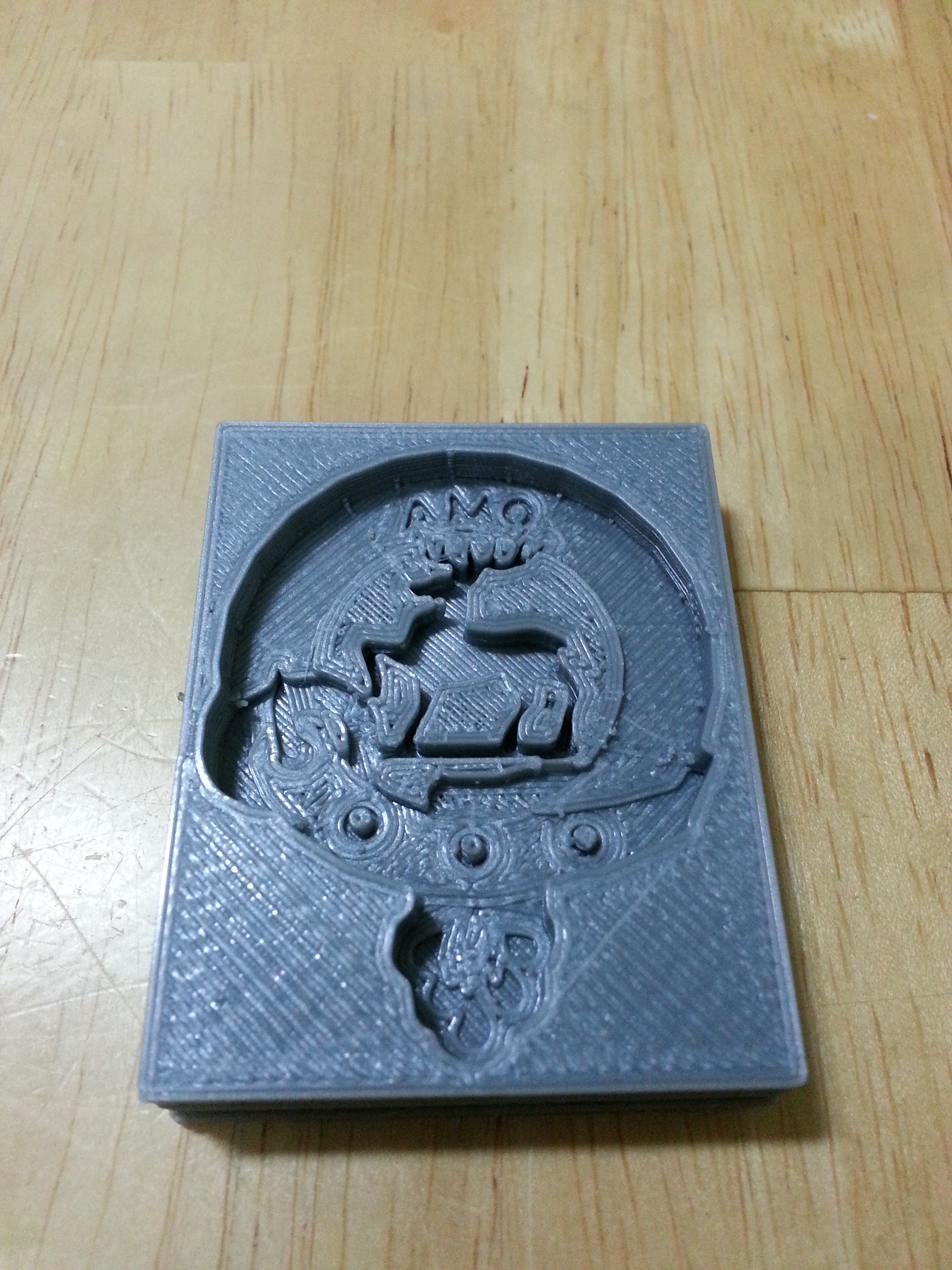
The item that I attempted to make was the crest/badge of Clan Scott.

Creating the 3D Digital Model
Since I only had a 2D image of the object I wanted to make a mould for, I had to make a 3D model before I could do anything else. I used the following steps in SketchUp to turn the above image into a printable .stl file:
- Import image
- Create a new layer to work in (Windows > Layer > +)
- Trace over the image with the line tool (circles and curves don't seem to automatically intersect so well)
- Draw a rectangular block that is bigger than the source image and extrude it to a thickness deep enough to contain the mould
- Paste the traced lines from step 3 (without the original image) on top of the rectangular block from step 4
- Calculate suitable depths (heights once cast) for each feature within the mould; for example, in the above image the stag is the most prominent feature so I extruded it to the greatest depth (but making sure to stay inside the rectangular block)
- Extrude different sections of the sketch to the appropriate depths determined in step 6.
- Export to .stl
Printing and Using the Mould
After I had the .stl file for my mould, I imported it into my 3D printer host software (RepetierHost), ran the slicer and printed it out.
The material I used this time to cast the finished product was Quickrete (repair mortar).
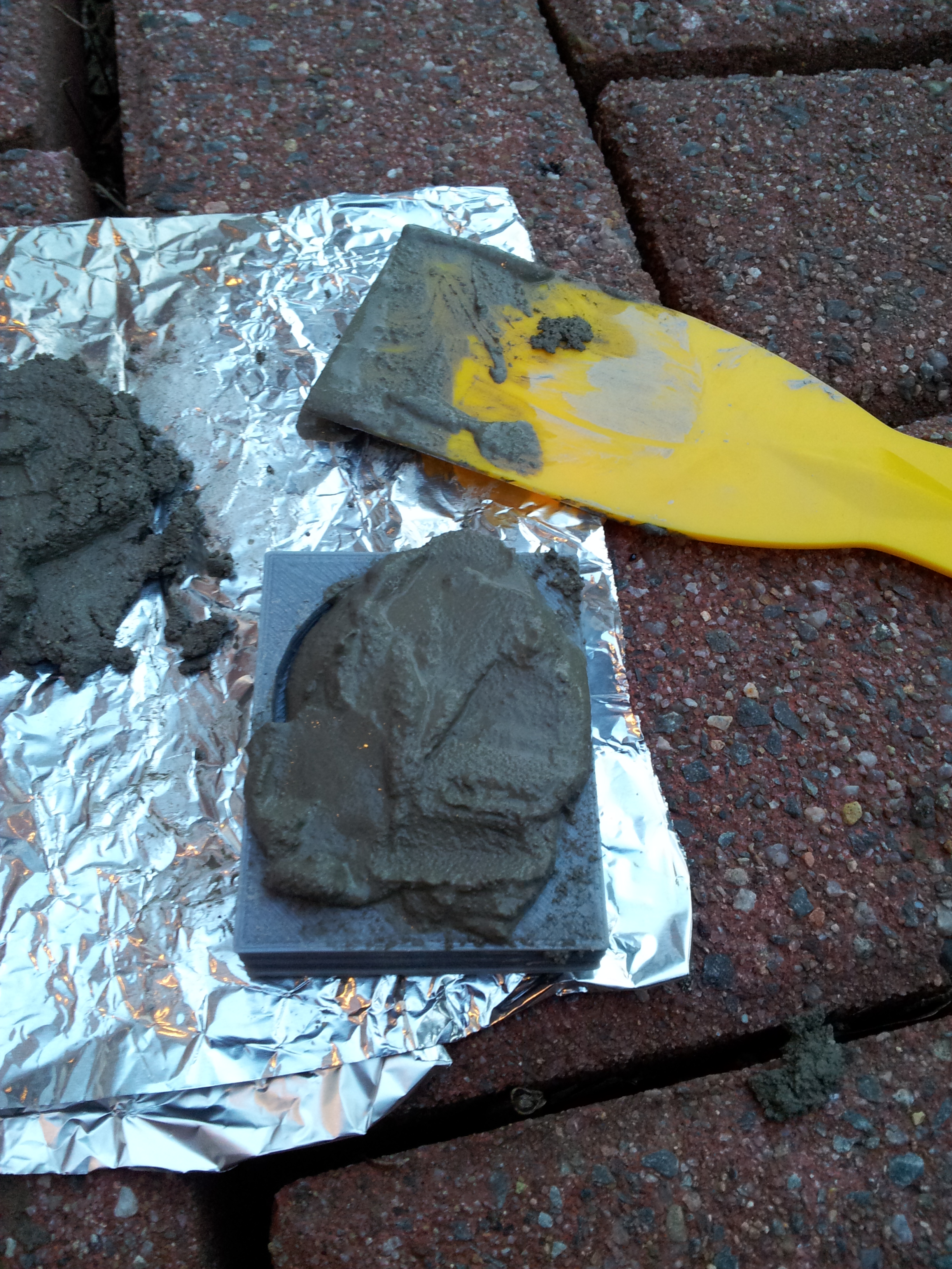
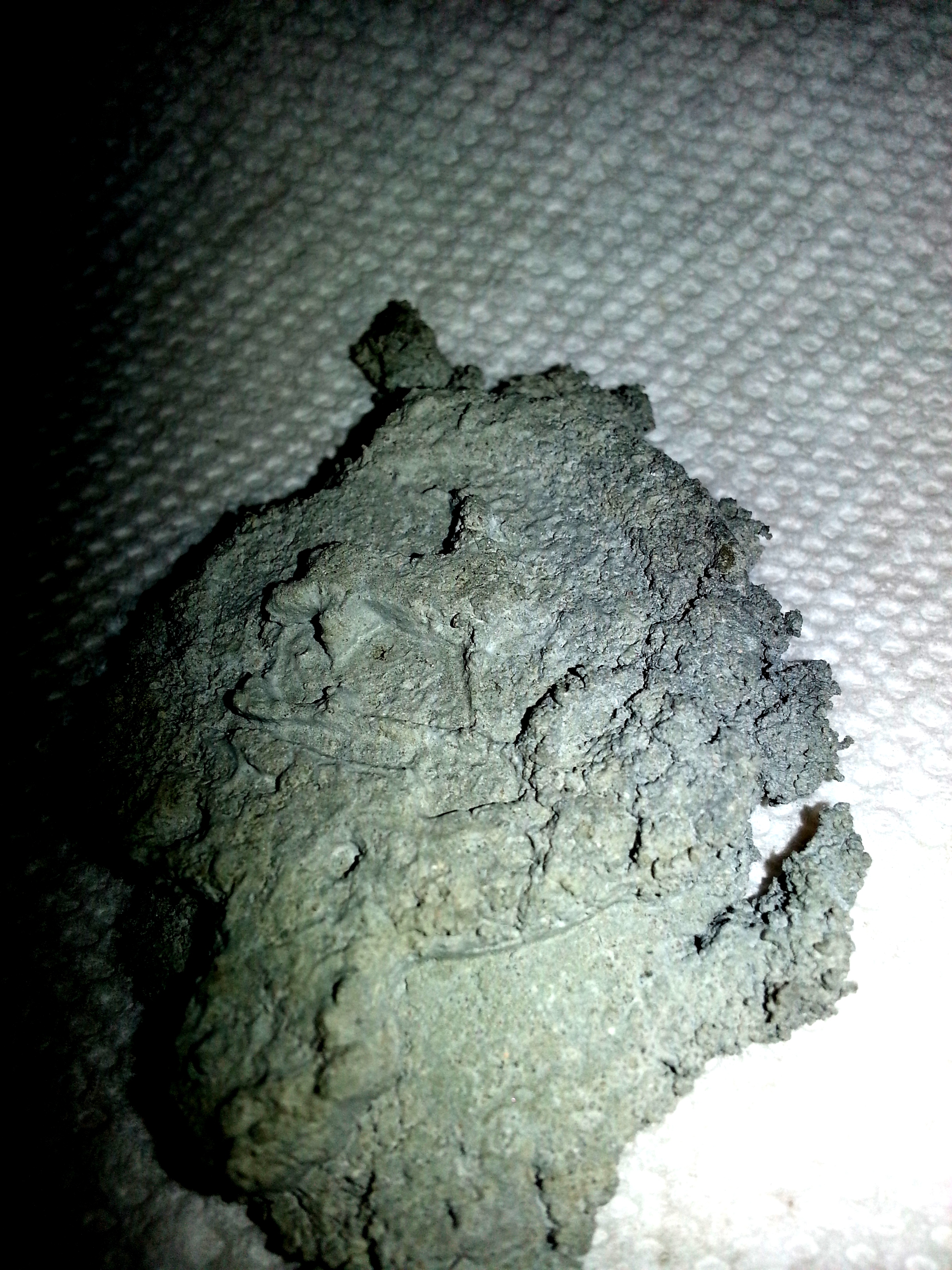
I cast two pieces with the mould. The first one was taken out of the mould immediately, while the second one was allowed to cure inside the mould. The first piece had a rough appearance as can be seen in the photo below and is missing a bit around the edges. It does make for a cool "archaeological find" effect, though. The second piece (not shown) was left to cure in the mould, which then had to be broken to get it out. It had a smoother appearance than the first piece but some details didn't show up very well and it cracked into several pieces while being extracted from the mould.
Lessons Learned and Future Things to Try
Overall, I think this technique has potential, although these pieces didn't turn out quite as well as I was hoping. After trying it, there are a number of things I'd do differently or experiment further with in the future:
- The image should have been mirrored before I traced it in my SketchUp procedure above. The text and the direction the stag was facing ended up backwards once it was cast.
- It might be more convenient to make a model of the finished object first, then do a boolean subtraction from a block to make the mould. This would save having to remember to mirror the image and invert heights/depths.
- The mould should be designed to make it easy to extricate the final product after it is cast (e.g. some slots in the side, or making the mould in more than one piece that could be taken apart to get the final product out).
- To get good results, it's probably helpful to have experience with the material being used. With cement-based materials, for example, optimizing the workability could make using a 3D-printed mould easier.
- There are many materials besides Quickrete that could be experimented with for moulding (e.g. polymeric clay, plaster of Paris, solder, etc.). Also, printing the mould itself out of different materials could benefit different applications. For example, a mould printed out of a water-soluble material would be very easy to get the finished product out of (with the tradeoff that the mould would not be very reusable).