A home-made probe for dissolved solids in water
Conductivity is a commonly-measured parameter in water. For example, I measured it in my thesis and it is being measured in the Disappearing Rio Grande Expedition. This post is about my first attempt at making a home-made probe to measure this parameter.
I've wanted to try making some DIY water-testing instruments for awhile. Now that I have a 3D Printer, it seemed like the time was right. I decided to try making a conductivity probe because it doesn't require any special materials. To measure parameters such as pH, oxidation-reduction potential (ORP), and ammonia or oxygen concentration would require specialized electrodes and/or membranes, but conductivity is inversely proportional to the basic electrical property of resistance (Ω). I already have a multi-meter that can measure resistance, so I just needed to make a probe with parallel electrodes.
Conductivity is a useful parameter, because it increases with increasing levels of salinity/dissolved solids. From empirical equations for ionic strength of solutions in Snoeyink & Jenkins (1980), I obtained the following relationship for Total Dissolved Solids (TDS):
I designed my probe to have electrodes with an area of 1 cm2 spaced 1 cm apart so that conductivity could be calculated as the reciprocal of resistance (which then needs to be multiplied by 1 million to convert Siemens to microSiemens).
Drinking water is recommended to have a maximum TDS concentration of 500 mg/L according to Health Canada Guidelines. Therefore I would expect my probe to measure a resistance of at least approximately 1.28 kΩ on tap water. At the other end of the spectrum, sea water has a salinity of 3.5% (35,000 mg/L), so I would expect to measure a resistance of around 18 Ω.
Making the Probe
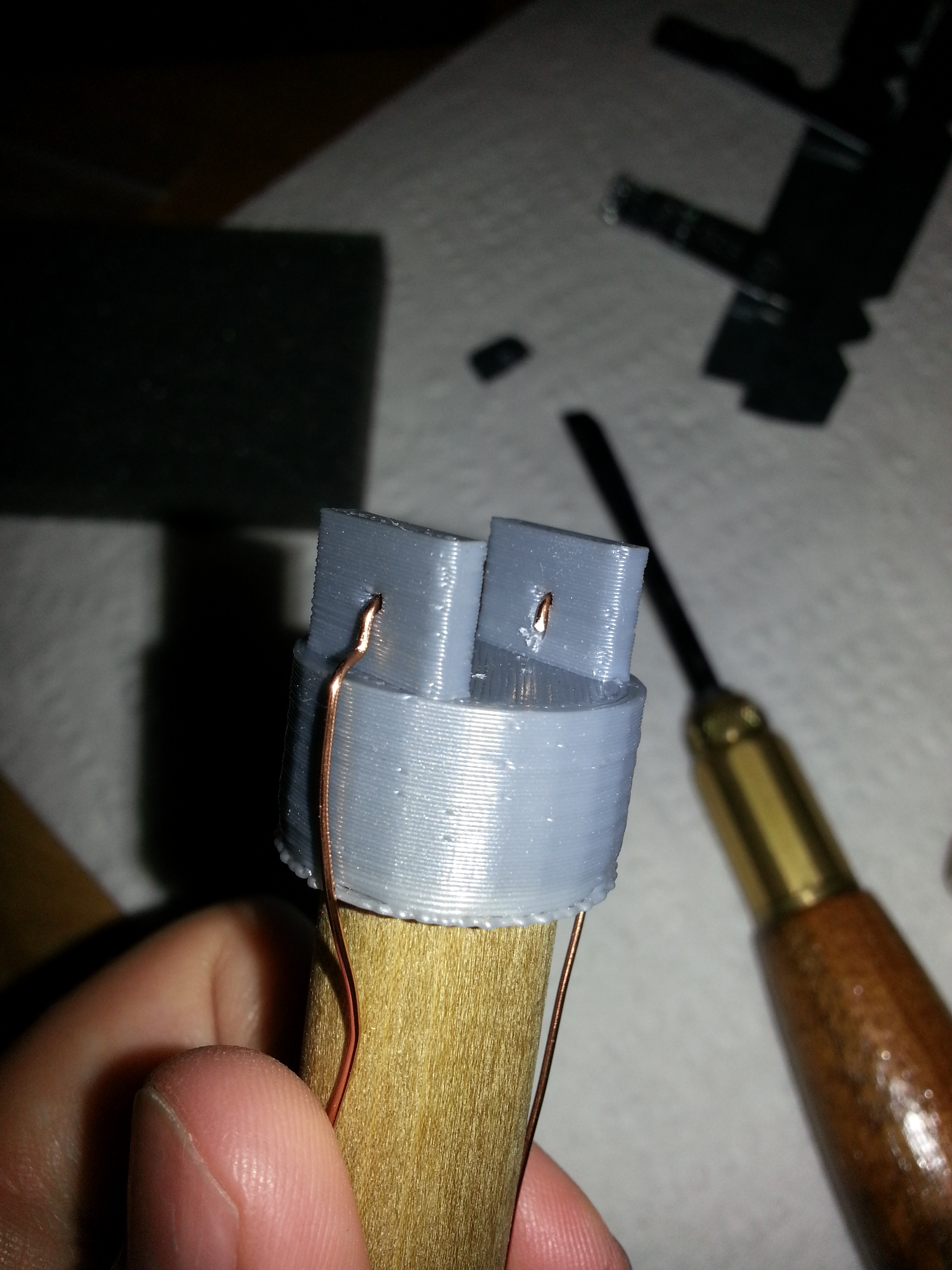
- I made a 3D model of a probe tip designed to space the 1 cm2 electrodes 1 cm apart
- I prepared metal plates with an area of 1 square centimeter (broken off of a random braket I bought for the purpose.
- I glued the probe tip to a wooden dowel (nominal diameter of 5/8" and inserted copper wires through the holes.
- At first I glued the metal plates to the 3D printed probe tip so that they were held tightly against the wire ends, but this didn't provide a good electrical connection, so I tried soldering the plates to the wires instead. Prior to soldering, I filed the surface to try to get a clean, un-coated spot for the connection.
- One of the electrodes still didn't have a good electrical connection to the wire. I've printed off a second probe tip to try again. The copper wire I was using seems to have some kind of coating, so I'll try using a different wire and hopefully be able to make a better connection.
- To give the probe a more finished appearance and to protect the exposed wires, I wrapped it in black electrical tape.
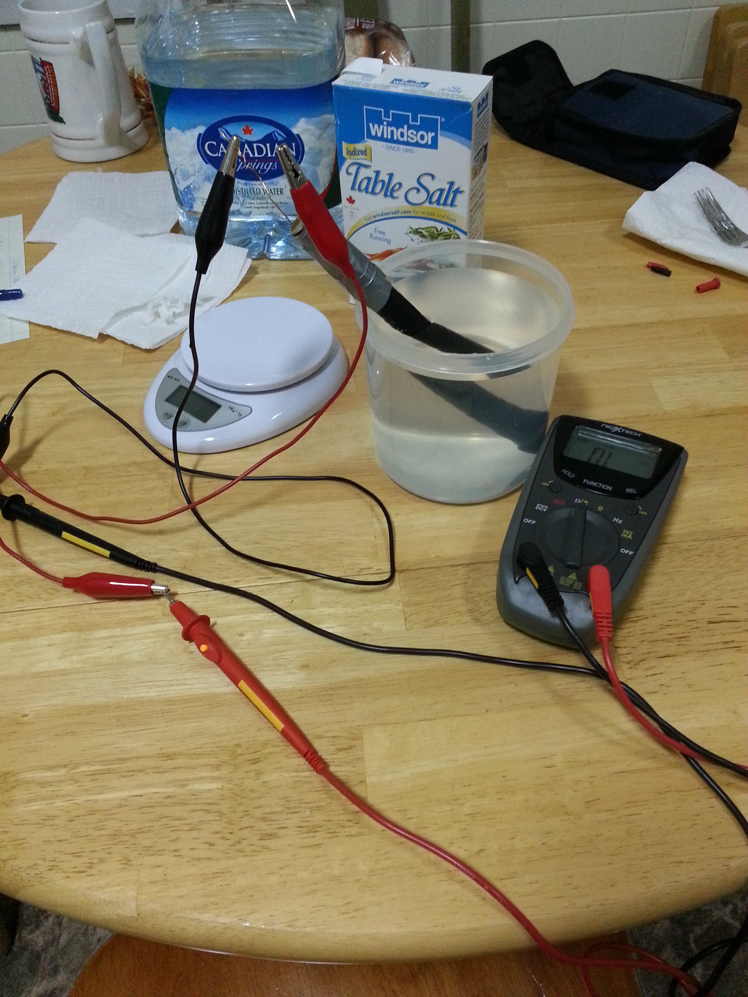
Calibrating the Probe
Above, I've listed some predicted resistances under different conditions, but in order to get better accuracy (e.g. in case the dimensions, spacing, or alignment of the electrodes is a bit off target), it is best to make a calibration curve. That is, I need to measure the resistance of prepared solutions (table salt in distilled water) of different salinity levels and perform linear regression on TDS vs. 1/R. Watch for a post covering this calibration—hopefully later this week (since this post is later than my normal posting schedule) if I can get a new probe ready by then.