Elementary Cellular Automata in a Hydraulic Computer
Despite the same word appearing in both titles, this post is quite different from the previous one. The inspiration for making the project described in this post came partly from re-reading Anathem last year.
A couple of books on complexity I read last year had some discussion on elementary (1-dimensional) cellular automata (in a different post I looked at 2-dimensional cellular automata). These are mathematical objects that consist of a row of cells that can be either on or off (values of 1 or 0). The state of each cell is changed by following a simple rule based on the states of its neighbours. The updated values are placed on the next row and the process repeats. Elementary cellular automata are interesting to study because the rules are very simple (so simple they can be represented by a single number between zero and 255) but they can exhibit very complex behaviour. See here for an introduction and a gallery of examples. One of the most famous rules, and the one I've worked with here, is Rule 110. Explaining what the number means is a good way to explain elementary cellular automata:
- For any 3 cells (the central cell of interest and its neighbours on the left and right), there are 8 possible patterns:
111, 110, 101, 100, 011, 010, 001, 000. - For each of the possible patterns, the updated value of the central cell will be either
1or0. - Listing the new values to be applied in the same order as the 8 patterns, Rule 110 is
0 1 1 0 1 1 1 0. - Converting this 8-digit binary number to base-10 is where the 110 comes from.
A hydraulic computer uses water instead of electricity to perform computations. The one I decided to try to build would take three inputs and output the updated value of the centre cell according to Rule 110. In order to select the correct output from various inputs, some kind of logic gate is required. I found a paper by Taberlet, Marsal, Ferrand, and Plihon (2018) that a type of logic gate that uses water. Here is the abstract:
In this article, we propose an easy-to-build hydraulic machine which serves as a digital binary computer. We first explain how an elementary adder can be built from test tubes and pipes (a cup filled with water representing a 1, and empty cup a 0). Using a siphon and a slow drain, the proposed setup combines AND and XOR logical gates in a single device which can add two binary digits. We then show how these elementary units can be combined to construct a full 4-bit adder. The sequencing of the computation is discussed and a water clock can be incorporated so that the machine can run without any exterior intervention. (emphasis added)
The full paper is behind a paywall, but the abstract was enough to give me an idea, since I've seen a siphon tower used to turn continuous flow into intermittent flow (with no moving parts) at a hundred-year-old wastewater treatment plant.
The design I eventually settled on is as follows:
- Six input cups (on the left in the image below). At first I wanted to make it with only 3 cups (for 3 cells), but I realized that in the case
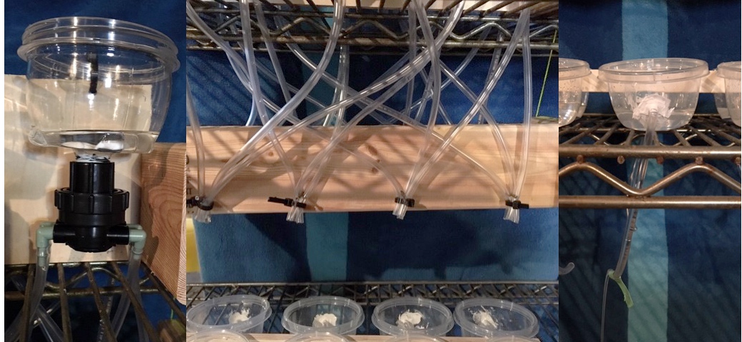
000(i.e. all cups empty) there would be no source of water. So each cell has a pair of cups, one representing1and the other (hidden behind a board) representing0. Each cup (the cups were dollar store food storage containers) has a 4-port distribution manifold attached to the bottom (with a drilled hole, a 1/2" threaded pipe nipple, a locknut, and some caulking)—this is because of the 8 possible patterns in total, there are 4 for each state of each cell. - From the distribution manifolds, 1/4" (outer diameter; 0.17" inner diameter) vinyl tubing goes to eight different positions (see the centre part of the image below). Each position receives flow from 3 cups (6 × 4 = 8 × 3) so all of the possible patterns are represented.
- Eight test cups are arranged underneath to receive the flow (on the right in the image below). Each test cup has a pin hole in the bottom (the "slow drain" referred to in the abstract) and a hole drilled in the side. The height of the hole is such that it will only be submerged if that cup receives flow from all 3 of the input cups that can potentially flow into it (the flow from each input cup is split 4 ways, so the hole in the side needs to be submerged when it has received 3/4 of the volume of an input cup). This hole has a tube passing through it (the siphon) with one end at the bottom of the cup and the other end dangling underneath the test cup. The dangling end of the siphon tubes that correspond to an output of
1are wrapped in green tape to distinguish them from the siphon tubes that correspond to an output of0. - Underneath everything, catching the discharge from the siphon tubes as well as the slow drains, is a tray to catch the water.
Here are some photos of these components:
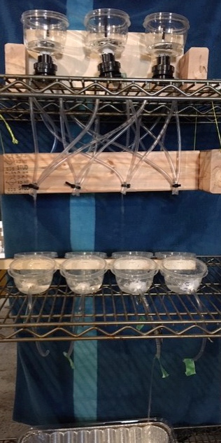
The way it is intended to work is that one cup from each upper pair is filled, to specify the input sequence. The water from these cups is distributed into 8 test cups. Only the test cup that perfectly matches the input sequence will have enough water to start its siphon flowing (basically the siphon has an "activation energy" threshold). Other test cups might receive flow from 1 or two of the input cups, but it will just discharge through the slow drain. Whether the siphon that does discharge is flagged with green tape or not indicates whether the output (i.e. the next state for the central cup) is 1 or 0.
Here is a picture of the complete apparatus, with flow being distributed to the test cups (there are only two streams visible because the water has almost run out of the upper input cups) and one siphon flowing:
I've been able to get each component working enough for a proof of concept, but so far the overall apparatus isn't really reliable. The flow doesn't get distributed evenly through the 4 tubes from each input cup. I think it needs more precision in having each tube terminate at the same level and perhaps larger diameter tubing to avoid air-locking. Neither the input cups nor the test cups will fully drain, giving them some dead volume so they aren't fully consistent (between cups or between runs). Again, more precision (or higher-quality materials) is needed. If the bugs could get ironed out, the next step would be to have a number of these assemblies in parallel. Each input cup would then need to have its volume distributed 12 ways (because it will act as the centre cell in one stack but the left-hand and right-hand cell in the neighbouring stacks and it needs a 4-way distribution for each stack)—so the precision requirements would be even higher. It would also be good for each stack to have a pair of output cups (rather than just flagging each siphon for their output value, they would be collected into the appropriate output cup); the pair of output cups could then be the input cups for a new row or could trigger pumping (from the drain tray/reservoir) back to the input cups in the top row.
The hydraulic computer presented in this post is a digital computer. Each input and output is either 1 or 0; either the level is reached for a siphon to start flowing or it isn't. However, probably the most famous example of a hydraulic computer was Bill Phillips' MONIAC, an analogue computer* for modelling the flow of money in a national economy:
*Analog computers work with continuous instead of discrete values. This article (which I've only skimmed due to its length) goes into their history.
Another video that may be of interest if you've read this far is this one of another Rule 110 computer that someone built with marbles (and much more precision than my efforts above with water):
Here are a few more links that may be of interest to wrap things up:
- A comic that imagines an elaborate simulation computed by an elementary cellular automata
- A linear mechanical calculator for the next row of Rule 110 (which also uses marbles)
- The Centre for Unconventional Computing
- An embroidered computer